The University of Washington's Interdisciplinary Honors Program offers its students opportunities to pursue extra projects in their major classes to double-count credit towards their graduation from the program. In Spring 2023 M E 478 (Finite Element Analysis), I was advised by Prof. Per Reinhall in a personal exploration of engineering analysis as applied in the medical devices field, using my own previous heart valve project as a test sample.
previous progress
In Spring 2022, as an Honors ad hoc project for M E 356, I designed a 3D-printable oval mechanical replacement aortic heart valve, informed by the design of existing metal valves and the range of materials and printing techniques possible to create valves less prone to failure.

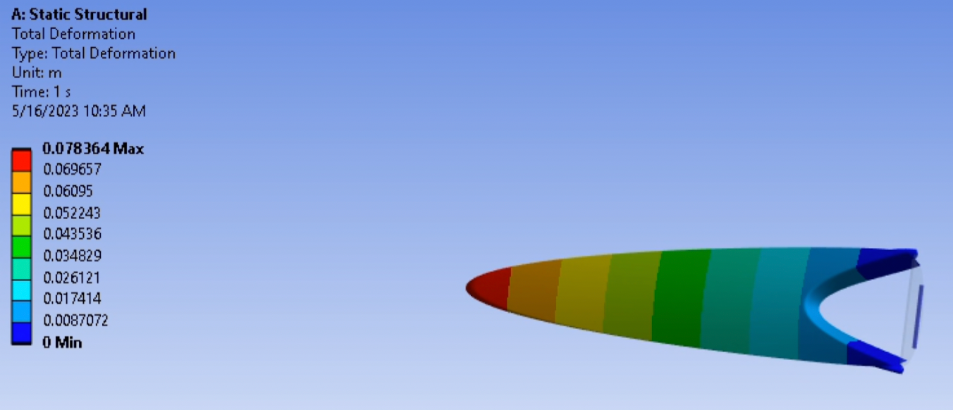
Isometric view of the top of a CAD model of the valve's final design iteration, with the leaflets shown in the open position

static linear (previous progress)
At the conclusion of the previous project, I attempted to verify the valve's resistance to blood flow forces, not only through manual linear-elastic analysis, but also through computational finite element analysis (FEA). By the end of last spring's project, I had only gotten an introductory overview of linear-elastic static analysis in ANSYS (the industry-standard software package for mechanical analysis), so I simplified the leaflet shape into a single beam by concentrating all forces into the center of the leaflet hinge.
As I described in my portfolio entry for that project, I got first hand experience in "garbage in, garbage out", as there were many variables that I didn't consider when setting up the analysis, the lack of which resulted in a 2000x larger deflection in the leaflet beam than the target maximum. This project served as a way for me to explore those variables deeper and use different analysis methods in the process, comparing results for similar systems between different methods. Are the design and material choices for this mechanical heart valve sufficient for long term valve replacement?

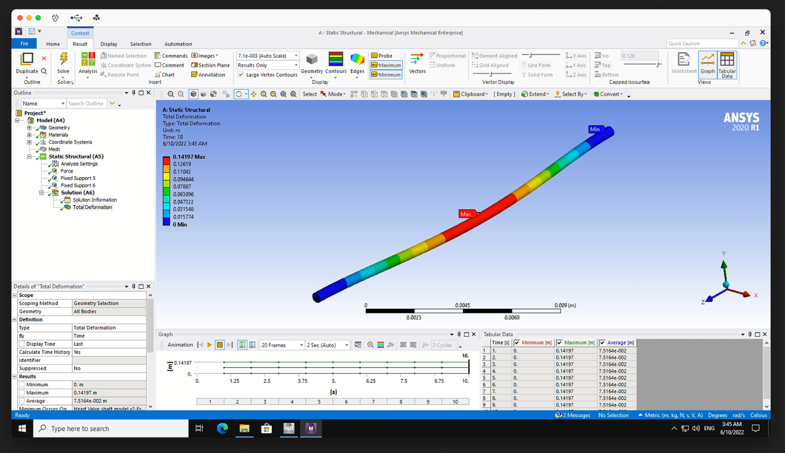
Screenshot of ANSYS Mechanical graphical user interface, showing a solution to a Static Structural deformation test on a shaft with the same dimensions as in the theoretical force analysis

static nonlinear
Linear analysis theory assumes that, relative to its dimensions, the part being analyzed does not deform a large amount due to the applied loads. However, if the valve were to be designed correctly, the force due to blood flow through the aorta would be enough to open the leaflets completely, meaning that they would be deformed a large amount.
Two toggles had to be changed in ANSYS Static Structural test settings to reflect this: 
• "Nonlinear Effects" —> "on"
• "Large Deformation" —> "on"
I tried this first with just the leaflet, with the existing resin material and the same pressure load as in the previous project (~18.6 kPa), which resulted in deformations far exceeding what's allowable. Modifying the resin material by increasing its Young's modulus by 100x resulted in deformations much closer to what's allowable. To me, this indicated that a material change was needed, so I switched from using a resin material to Ti6Al4V, a titanium alloy used in laser powder bed fusion (a common metal 3D printing process).

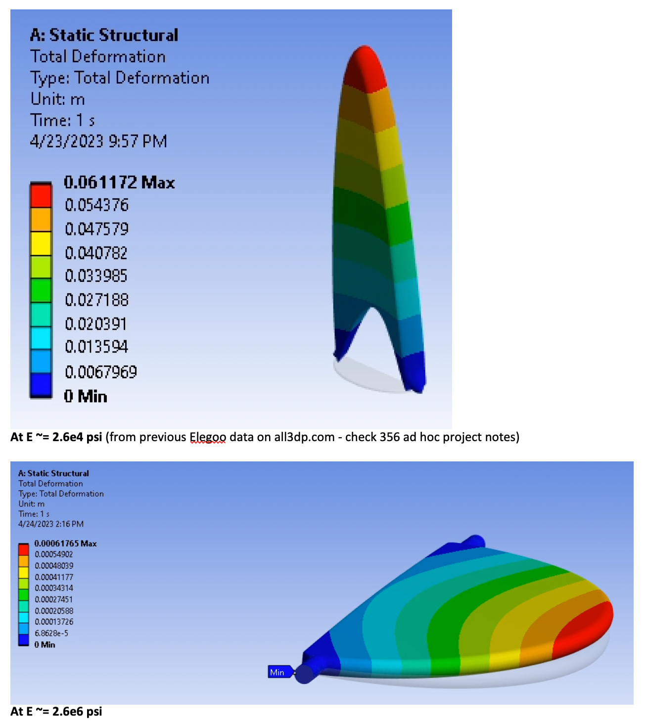
Screenshot of OneNote page showing static nonlinear deformation analysis results before (top) and after (bottom) 1e2 increase in E

At this point, I wanted to move closer to simulating blood-flow forces through the actual leaflet, so I added a thin and long Ti6Al4V block to model the heart valve enclosure ring's bottom stopper ring that the leaflet collides with during the diastolic (relaxed) phase. I ran a similar test with the existing resin material (pictured), marking the region of contact between the leaflet and block as "frictionless," and found that deformations were similarly large. Doing the same test with Ti6Al4V showed similar reductions in deformation.

Static nonlinear analysis of resin leaflet colliding with block upon downward application of force. Something is clearly wrong here, as material changes fixed it...

implicit dynamic
Static analysis methods assume that the state of the part being analyzed does not change with time. This is a good simplification for linear-elastic material property testing, but it breaks apart when considering that the leaflets are supposed to open and close for the systolic and diastolic phases of heart pumping, respectively. This fact, by definition, makes dynamic analysis necessary to progress closer to the real design and loading scenario in the aorta.
In the simplest terms, dynamic analyses string together many static analyses to simulate changes to the part over time, solving not only the system's inherent stiffness matrix (like in static analysis), but also any non-zero matrices representing masses and damping. In turn, implicit dynamic analyses assume a short ("transient") time interval within which the system changes. This lends itself well to analyzing the impact of the leaflet hitting the stopper lip. 
I got too excited and jumped straight into attempting to run an implicit dynamic analysis on the entire leaflet using ANSYS's Transient Structural tool. The associated user interface (pictured below, left side) tricked me into believing that it's not possible to input usual loads and constraints with this tool, so I instead opted to play around with contact regions and initial velocity conditions to apply a load. This resulted in an incomplete solution (pictured below, right side).

Incomplete results and the objects used to generate them

As a result, I took a step back and returned to analyzing the leaflet hitting the block, with the same constraints, boundary conditions, and loads applied through the Transient Structural analysis tool. I found that the deformation results (pictured next) were close in quantity to the nonlinear static analysis previously conducted, small enough to qualitatively verify its accuracy. However, this small deformation upon the ramped application of pressure is worrying, as the pressure should open the leaflets the entire way up, not just slightly partway like these deformation values are indicating.

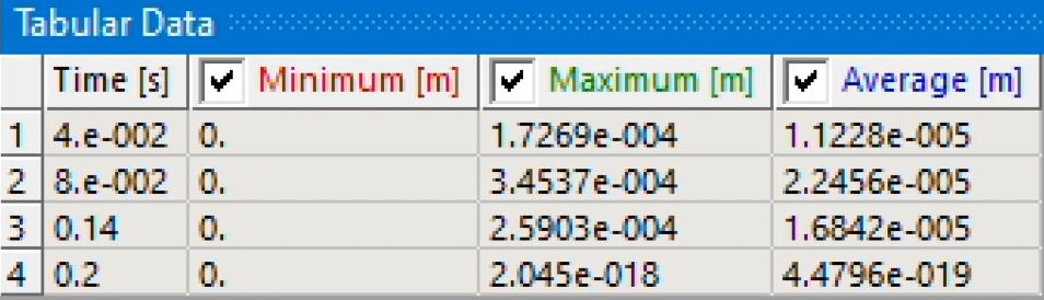
Minimum, maximum, and average leaflet deformation values on the leaflet using Transient Structural analysis

This is where things began to break down for me. 
I returned to the whole-valve model to redo the implicit dynamic analysis on it. This time, I changed the following properties about the setup:
• Both parts of the outer ring set to rigid flexibility behavior
• Fixed Support applied to the bottom surface of the outer ring
• Hinge ends of leaflet are not fixed
• Bond the two halves of the outer ring together and add frictionless contacts between the leaflets and the bottom stopper lip
After running the analysis (for 36.5 hours) and seeing the leaflets pop out of their hinge, Prof. Reinhall and I realized that I forgot to change one thing: include frictionless contacts between the leaflets and the top half of the outer ring. ANSYS treated the top half as if it didn't exist, allowing the leaflets to pop right out of their sockets!

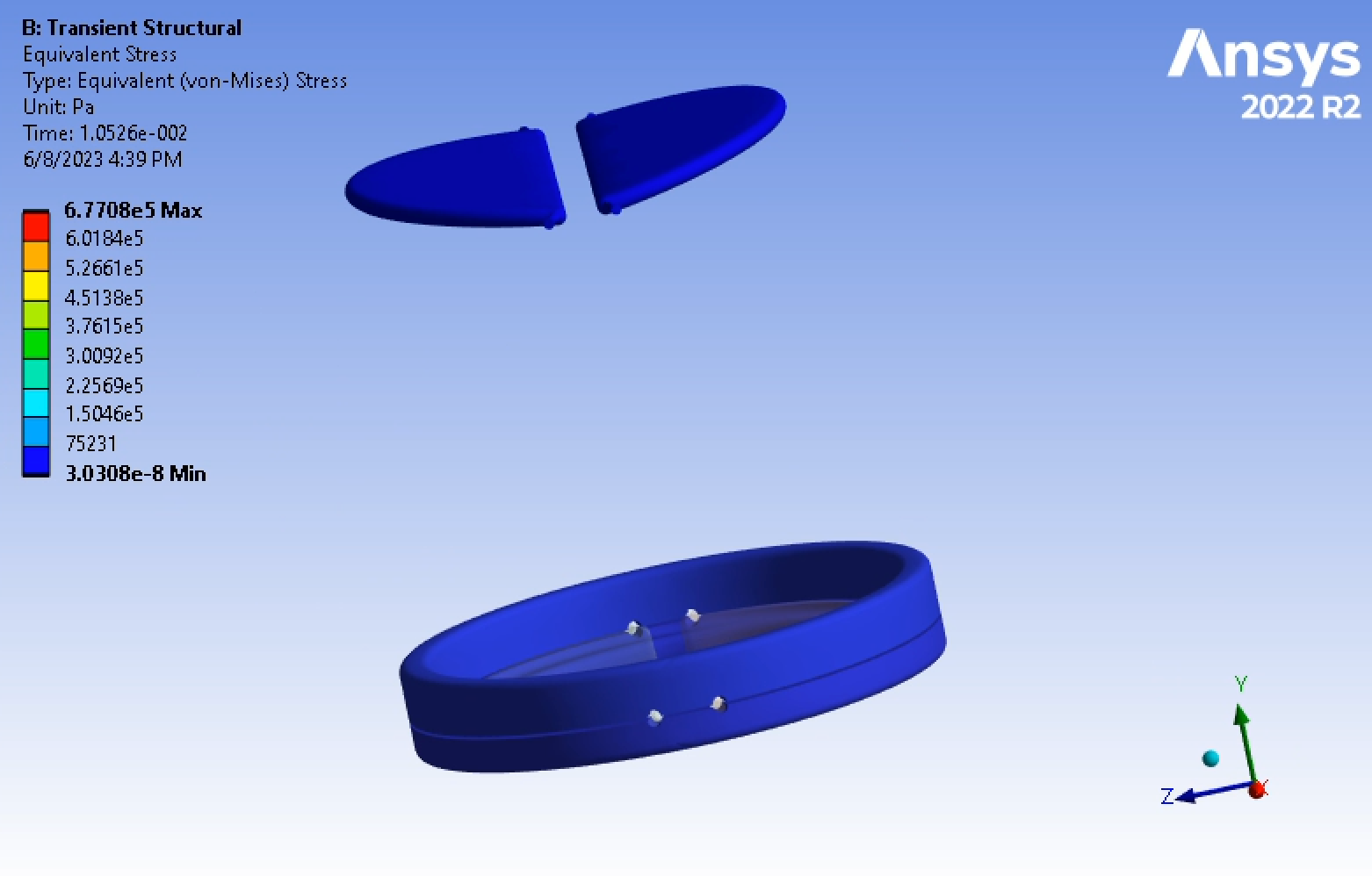
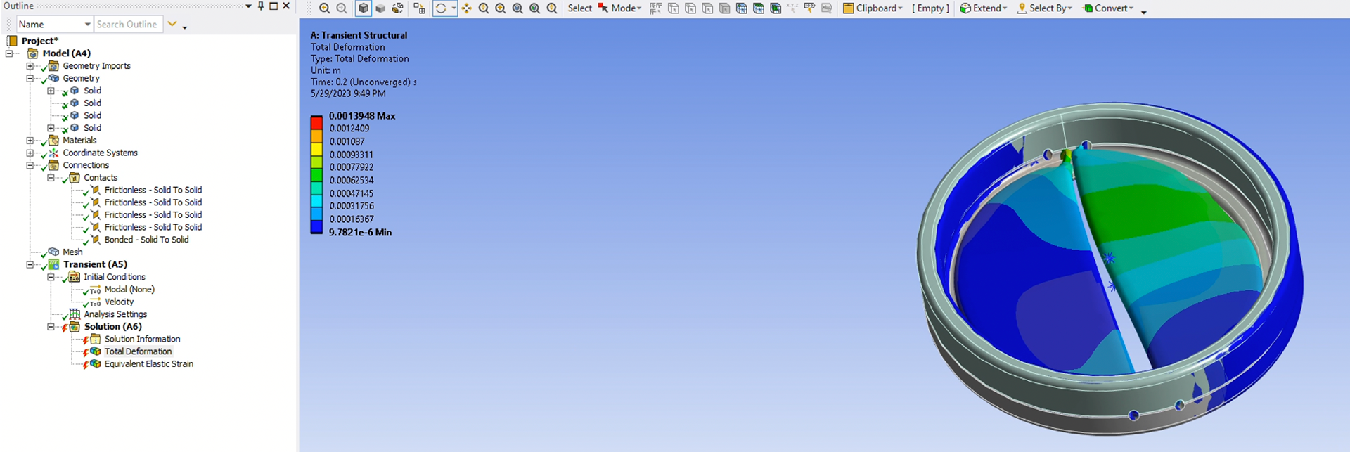
Third iteration of Transient Structural results, just two frames into the 0.2-second simulation period (representing a full ramped systolic load)

explicit dynamic
In contrast to implicit dynamic analysis methods, explicit dynamic analysis methods (put simply) work well for dynamic systems that shift in state over a larger time scale, making them theoretically perfect for simulating the leaflets going through a full opening and closing state. That is, they would be perfect if I was able to access the Explicit Dynamic analysis module for use in the full leaflet model instead of being stuck in read-only mode due to licensing restrictions, as shown below.

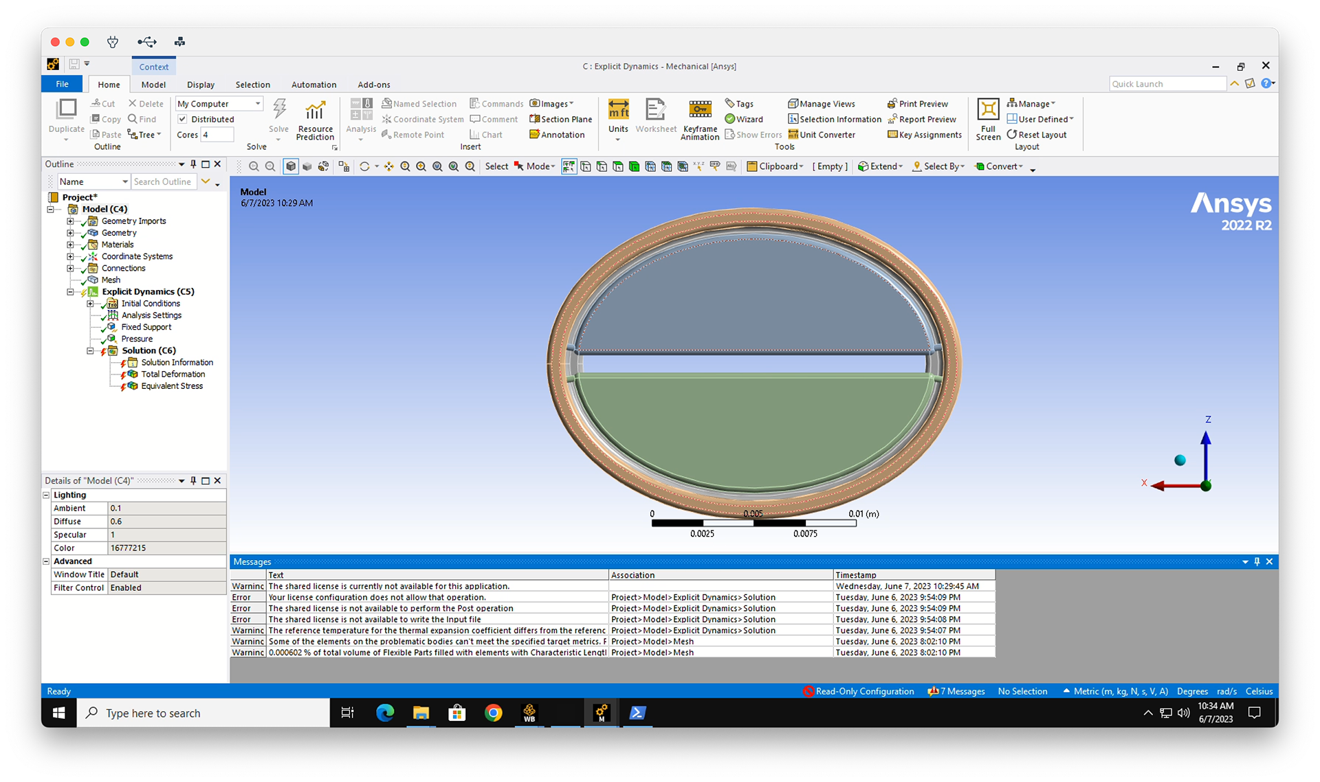
No amount of troubleshooting on my end could resolve these errors and the "Read-Only Configuration" tag on the bottom of the ANSYS window

recommendations
The parts of this analysis that did function yielded a few design changes to implement:
• Straighten leaflet stub hinges into a single flush bar to reduce stress concentrations and out-of-plane moments
• Use powdered Ti6Al4V with powder bed fusion instead of photopolymer stereolithography resin to additively manufacture heart valve components. This opens up the possibility for parametrizing this model to fit different aorta dimensions
• Once the material is changed, reduce the thickness of the leaflet so that it resists blood flow less and can more easily open fully, as current stresses are substantially under yield strength

next steps
If I had more time, these are limitations in this analysis that I would fix:
• Simplify ring geometry to allow for shorter analysis times while still enabling investigation of leaflet-ring impact physics
• Remake the ANSYS Workbench whole-valve file to further troubleshoot issues with the Explicit Dynamics analysis tool
• Slice the leaflet stub hinge geometry into quadrants so that a single central node can be made into a Fixed Support (rather than the whole end face of the hinge), enabling rotation to be simulated through the entire hinge rather than forcing twisting

acknowledgments
Many thanks to Dr. Per Reinhall, Professor in Mechanical Engineering at the University of Washington, for invaluable and unwavering guidance in modeling, patience with my senioritis, and willingness to connect me with professionals using FEA in medicine and electronics.
Thanks to Anya Prasad for much-needed moral support (and occasional technical support).

Back to Top