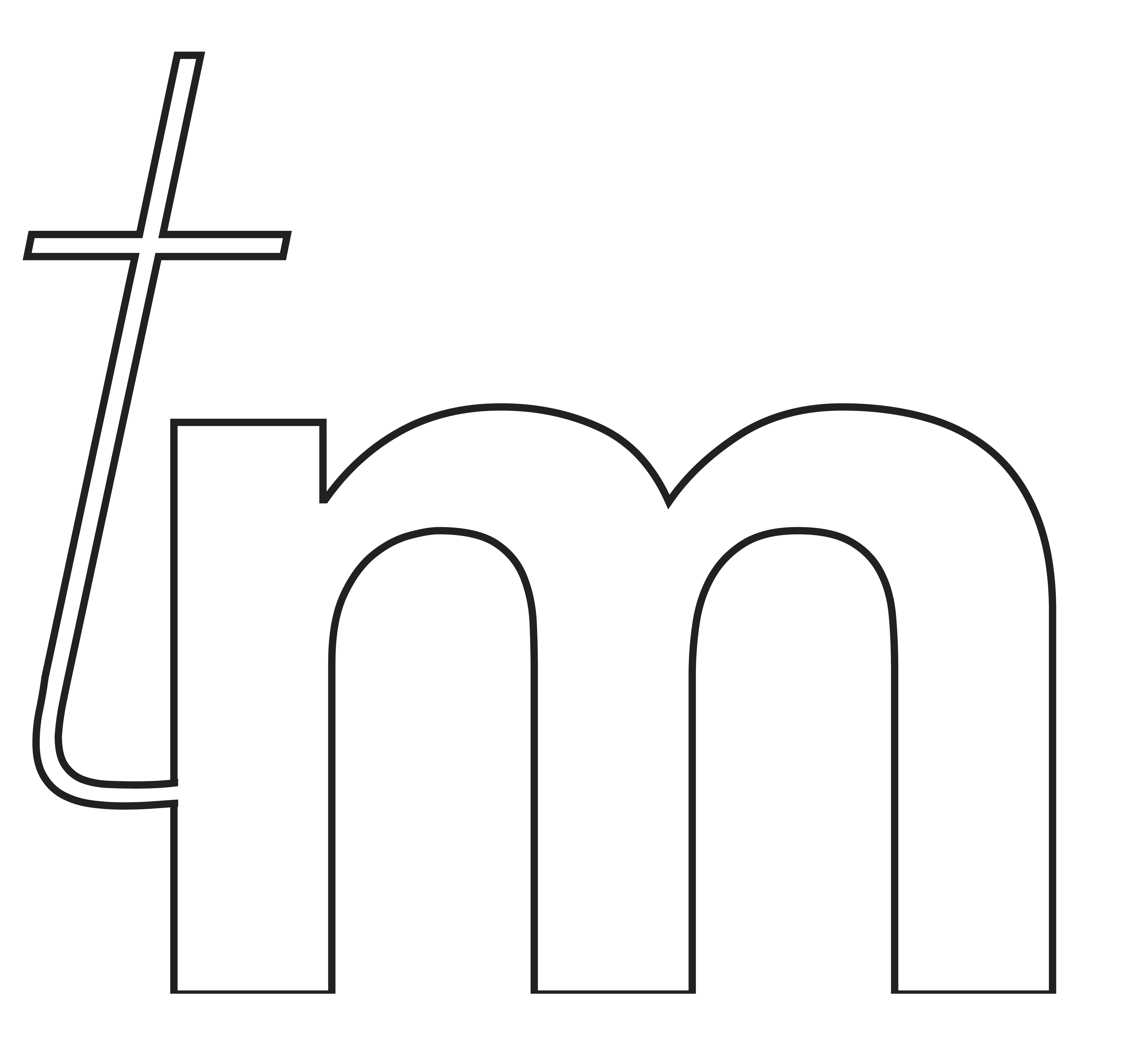

Isometric view of a CAD model of iteration 1, with dashed lines showing invisible bileaflet and hinge contours (modeled in Fusion 360).
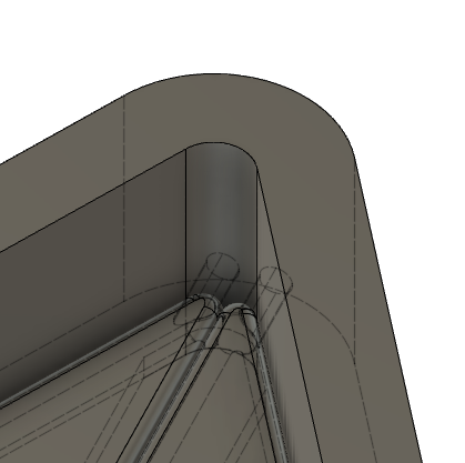
Close up view of narrow hinge of a CAD model of iteration 1, with dashed lines showing invisible bileaflet and hinge contours
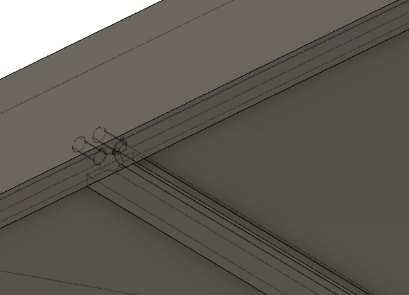
Close up view of wide hinge of a CAD model of iteration 1, with dashed lines showing invisible bileaflet and hinge contours
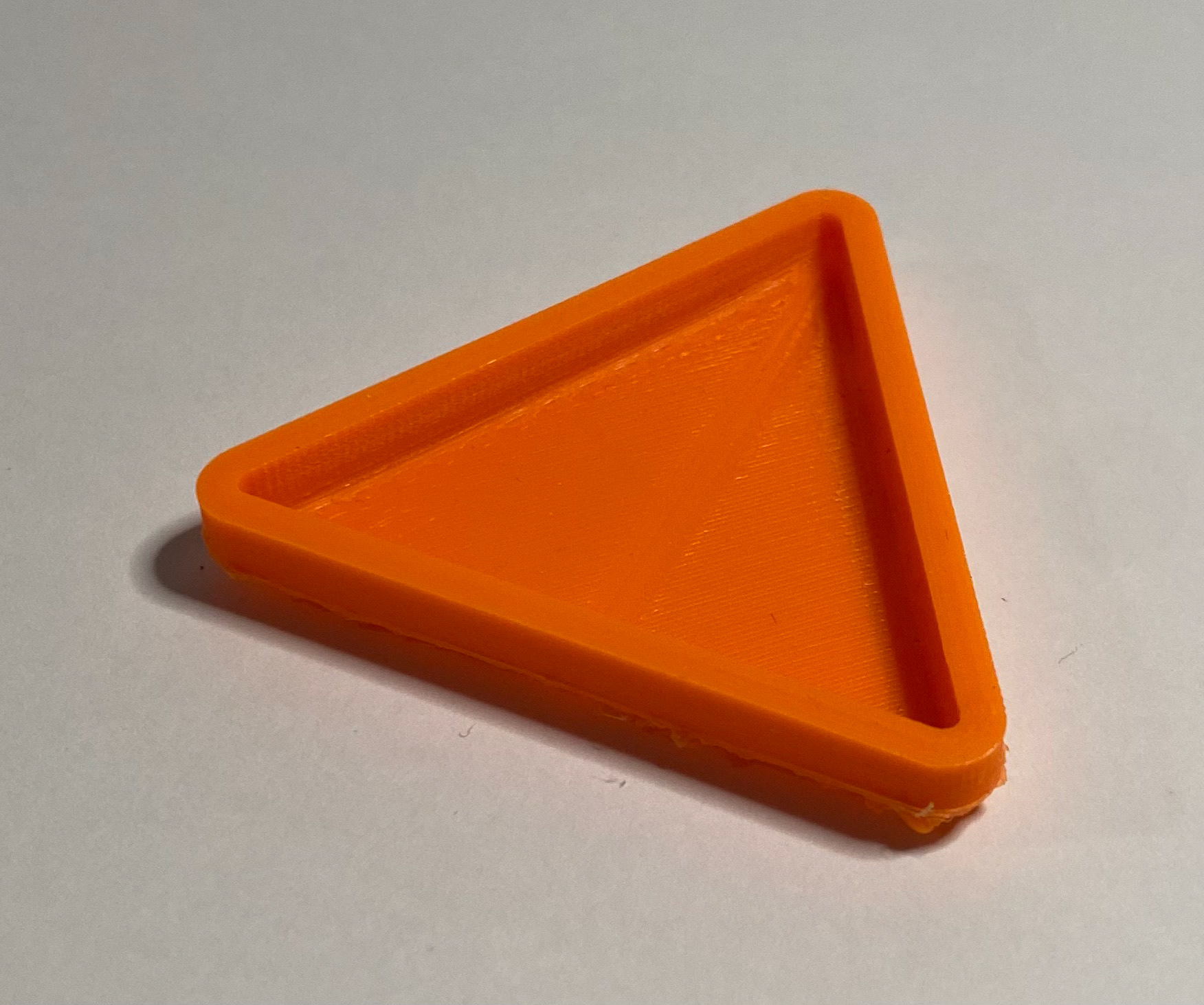
Top side of 3D-printed iteration 1 (2x scale), showing filled-in gaps where there should be openings in model
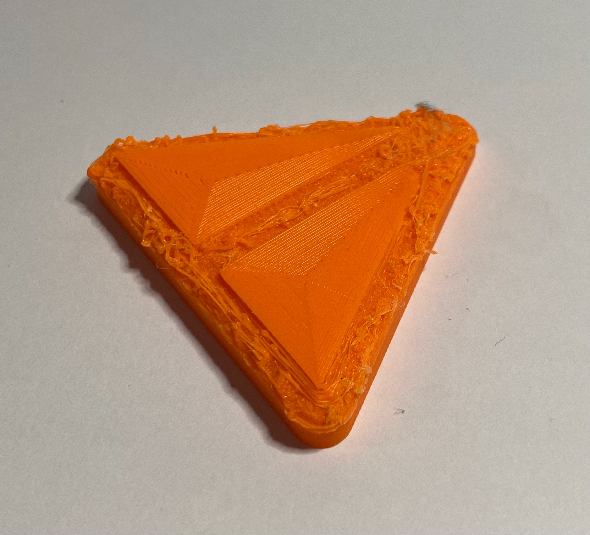
Bottom side of 3D-printed iteration 1 (2x scale), showing bileaflet scaffolding present in model almost entirely missing from print
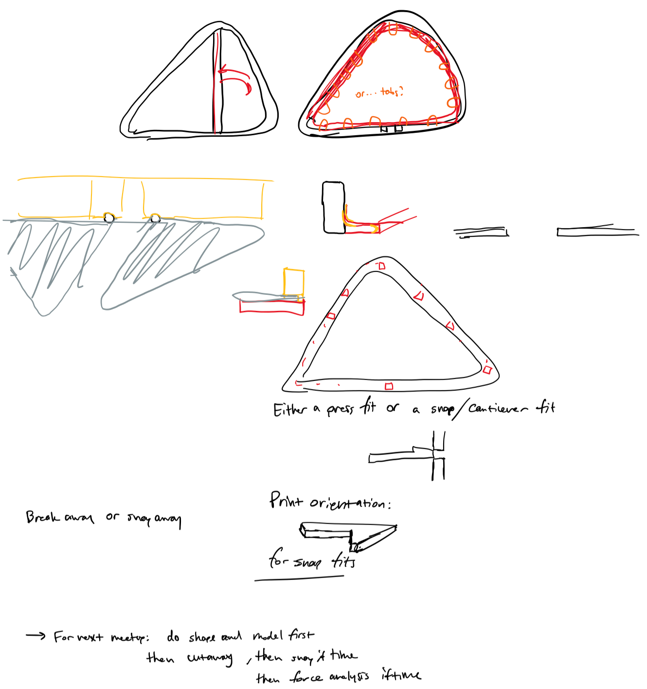
Notes from the meeting preceding the development of iteration 2, exploring potential alternatives to printing hinges in place.
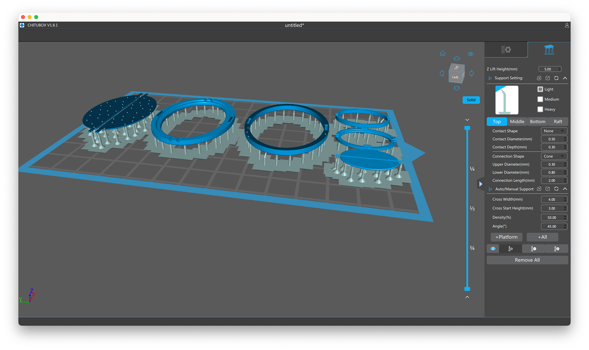
A screenshot of CHITUBOX's graphical user interface with 1x and 2x scale cut-open models of iteration 1, intended to be press-fit together, put onto a virtual 3D printer buildplate. The CHITUBOX software package automatically adds supports onto 3D printer beds, making prints higher quality and much easier to detach from the buildplate before beginning post-processing.
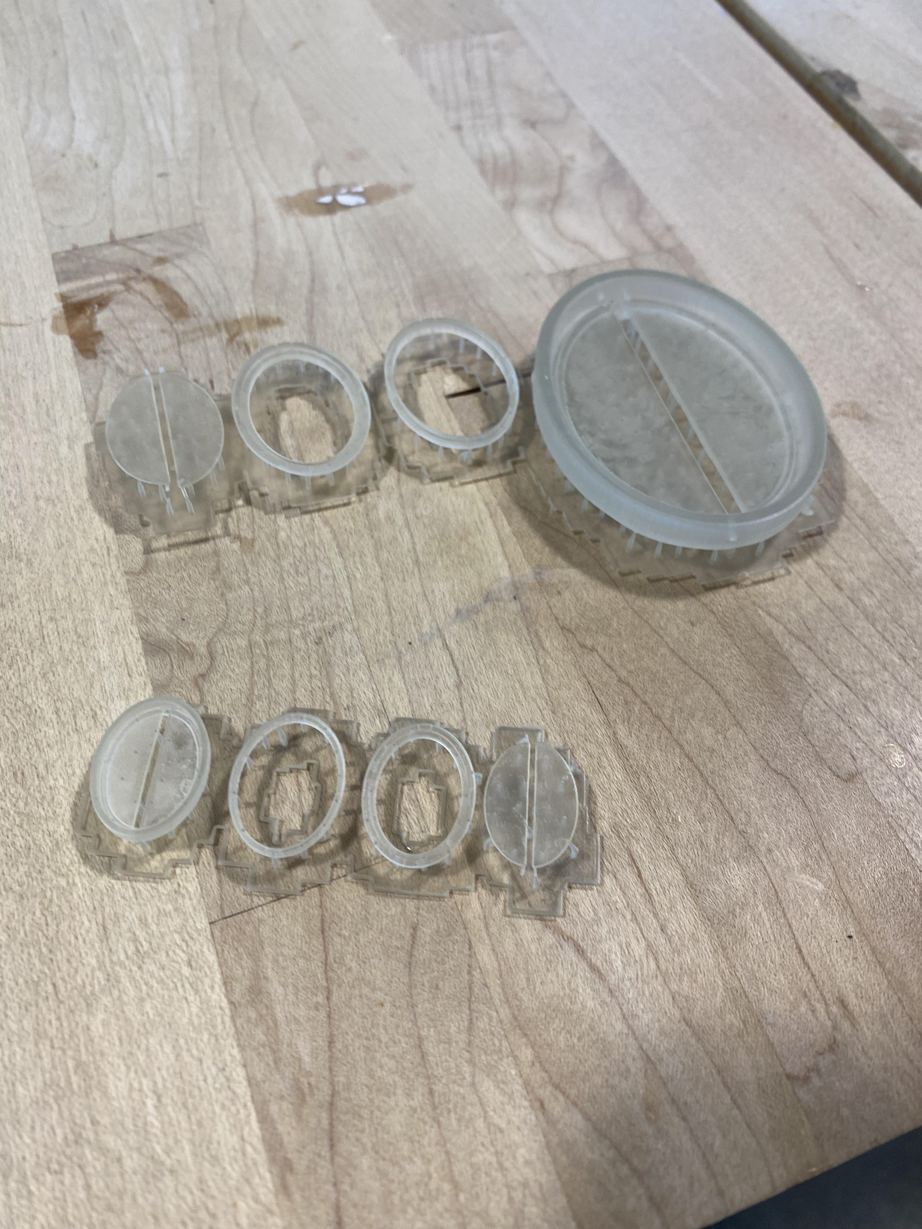
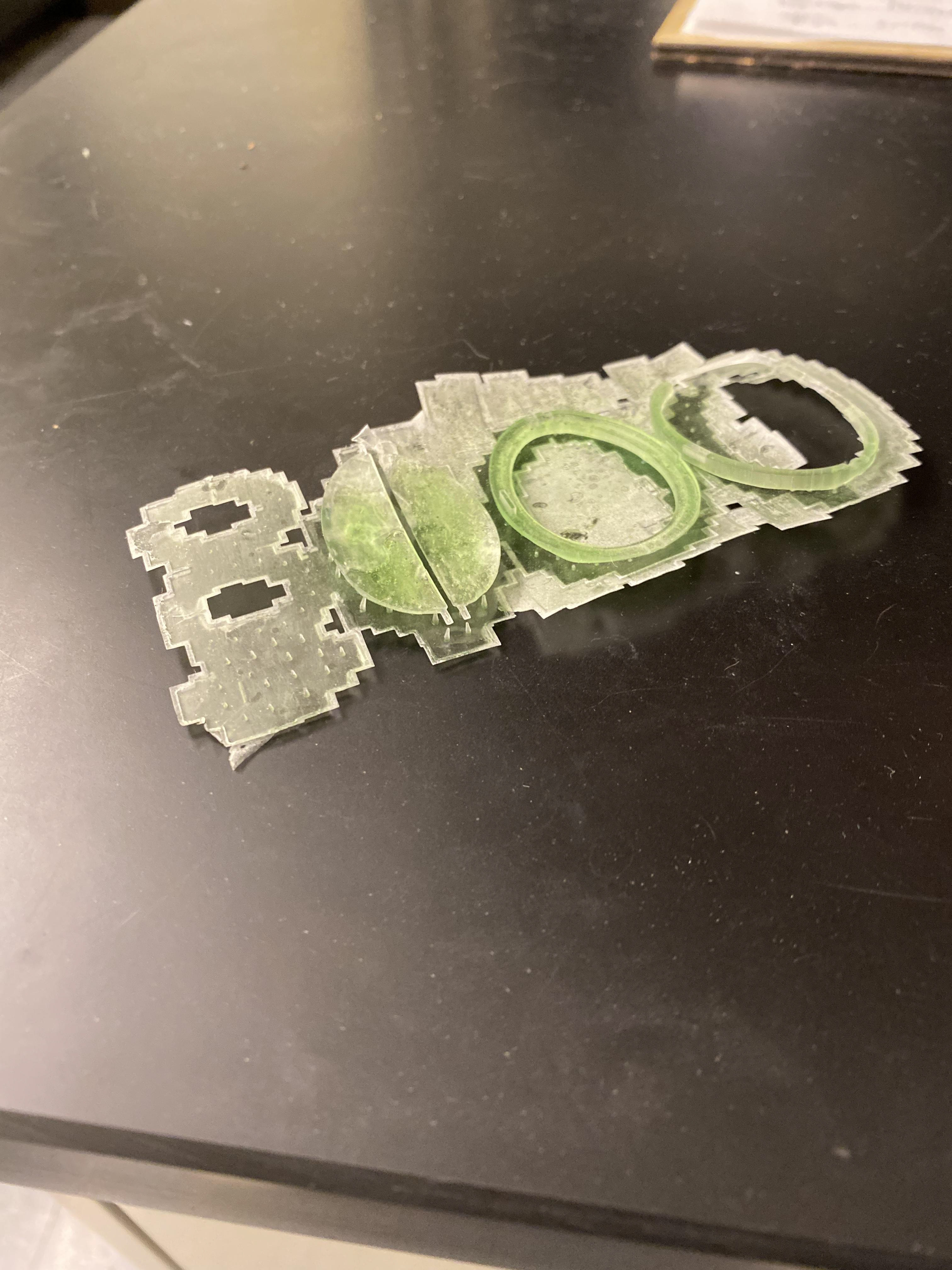
Cured and processed prints of iteration 2 (1x, 1.2x, and 2x scale) done near the halfway mark of the project, with all components still attached to supports.
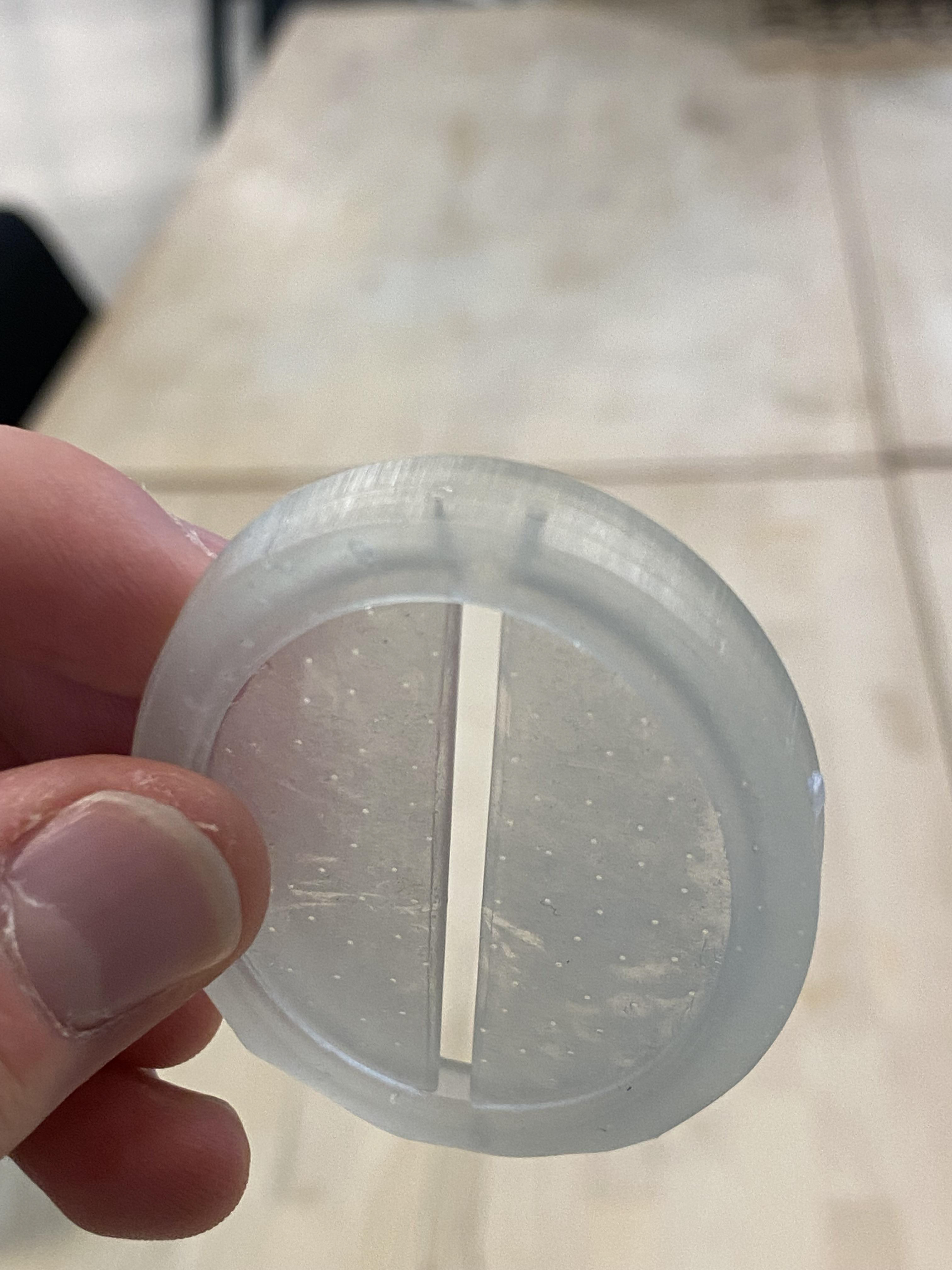
A close-up of the printed-in-place hinges on the 2x scale model of iteration 2, showing that although the hinges are visually distinct inside the frame, the cavities are still too small so the hinge fused to the frame during printing.
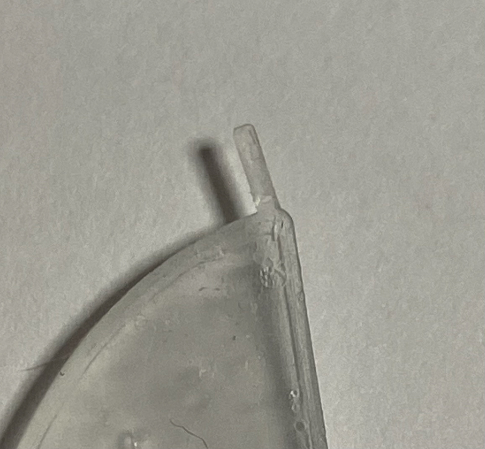
A close-up of a hinge on a 1x scale model of a leaflet in iteration 2, showing its offset from the central axis of the overall design. This offset resulted in a rotational moment being engaged onto the hinge when the leaflet rotated out of position, making it more susceptible to fracturing earlier than the rest of the part.
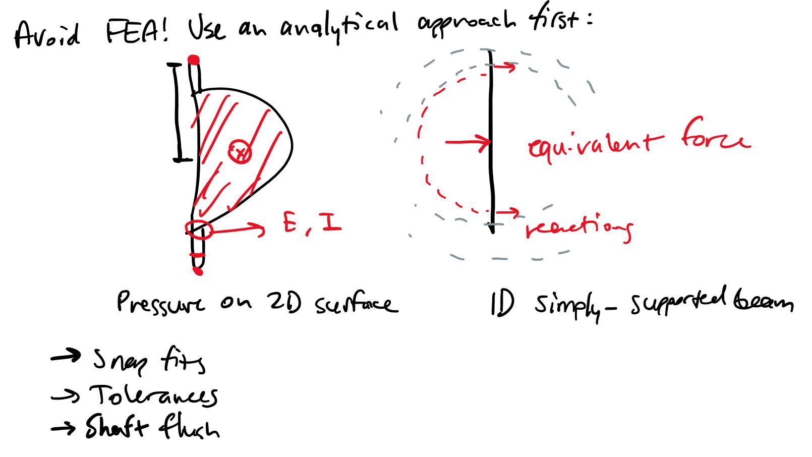
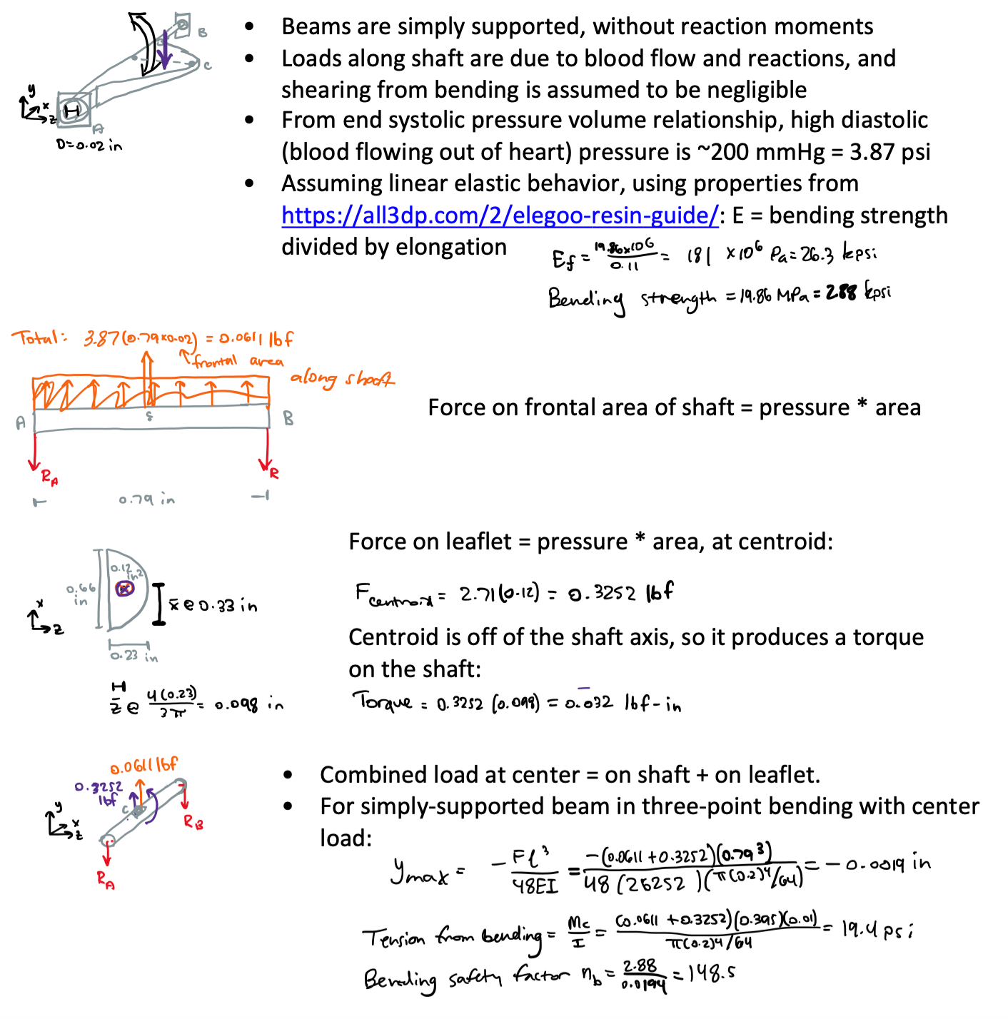
Notes from the meeting preceding the development of iteration 3, outlining options for manual force analysis through linear-elastic assumptions.
A 3D print that failed from bad adhesion, as shown by parts missing from the tops of support structures on the left and uneven thickness of parts on the right, after post-processing.
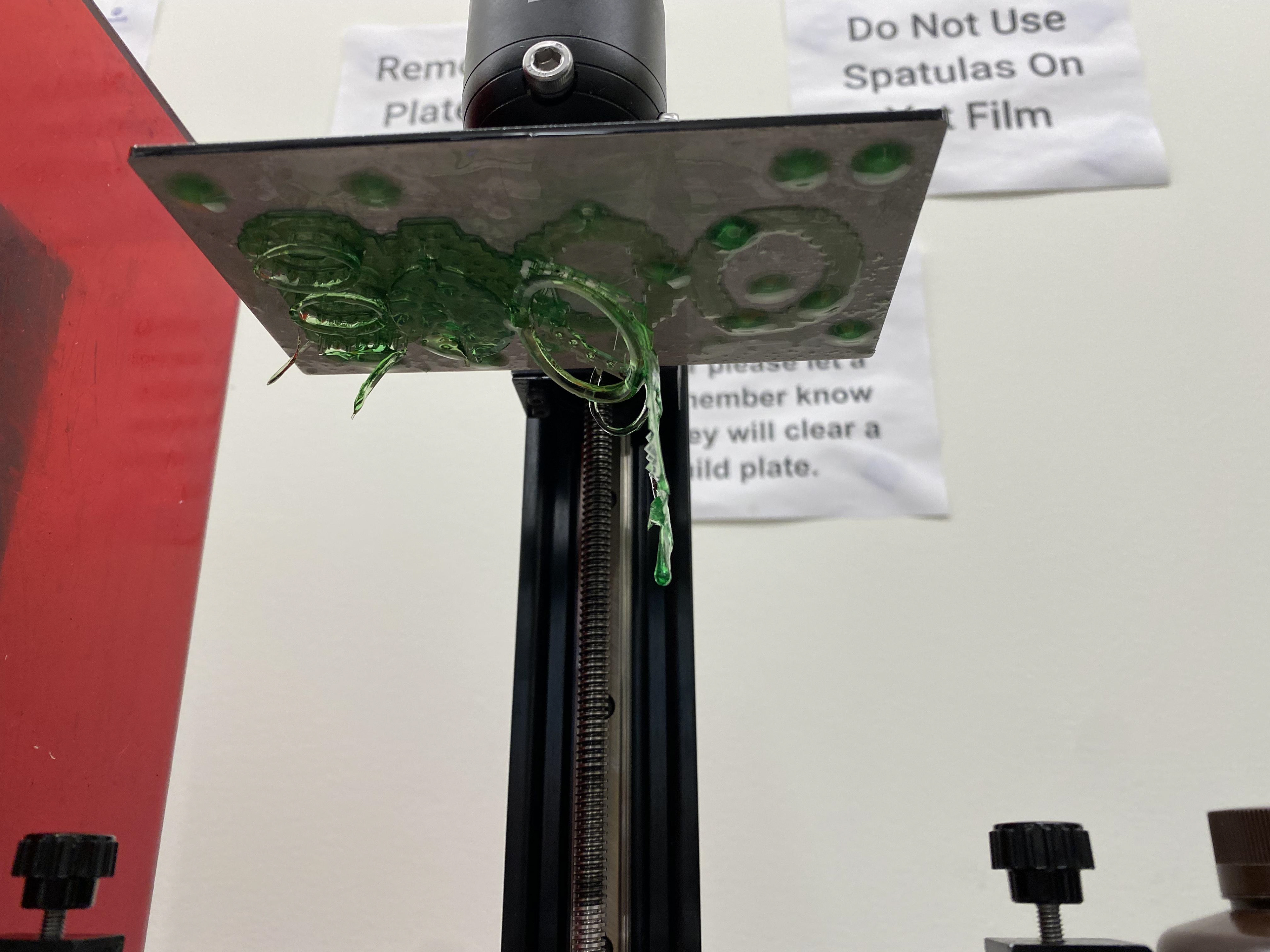
A 3D print that failed from bad adhesion, as shown by parts missing from the tops of support structures on the right and uneven thickness of parts on the left, immediately before post-processing.
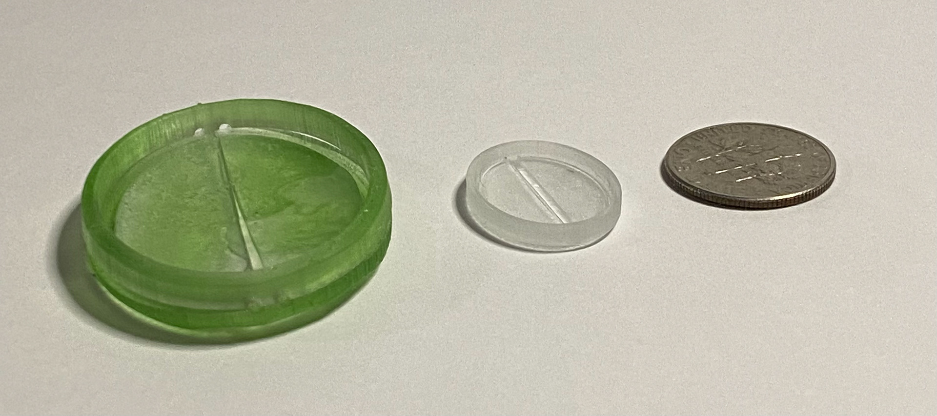
A 2x scale model of iteration 3 (left) compared to a printed-in-place 1x scale model of iteration 2 (middle) and a dime (right), showing the small sizes of features bearing forces resulting from blood flow.
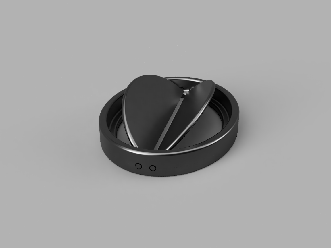
Isometric view of the top of a CAD model of iteration 3, with the leaflets shown in the open position.
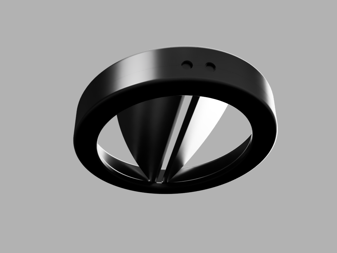
Diagonal view of the bottom of a CAD model of iteration 3, with the leaflets shown in the open position.
Short animation of press-fit iteration 3 assembly.
Close-up view of the parallel hinges in iteration 3, from above.
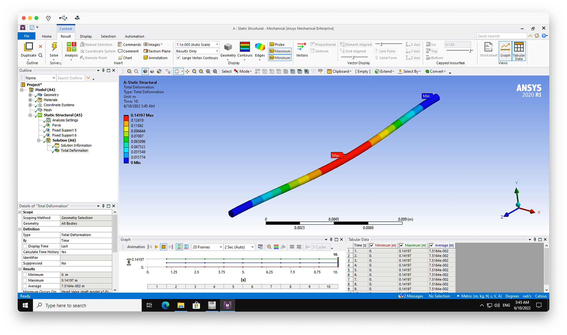
Screenshot of ANSYS Mechanical graphical user interface, showing a solution to a Static Structural deformation test on a shaft with the same dimensions as in the theoretical force analysis